40kV Cascade
The first high voltage cascade was build by using 10nF 2kV capacitors and a series of 3 1N4007 rectifiers in series. It has 20 stages resulting in a maximum output voltage of 40kV. To ensure an even voltage distribution between the rectifiers, a voltage divider with 10M resistors is added in parallel. This has also the advantage, that the cascade will discharge quickly when it is powered off. For every stage, corona rings were added, even if they are not necessary at these voltages.
The driver was based using the ferrite core of an old flyback transformer, with self-winded primary and secondary coils. It was powered by the common 2N3055 feedback circuit. Even though the circuit is fairly simple, it is quite hard to simulate with a cascade as a load. The feedback of L2 is not only influenced by L1, but also by the load of L3. This causes LT-Spice to decrease the step width until it crashes.
200kV Cascade
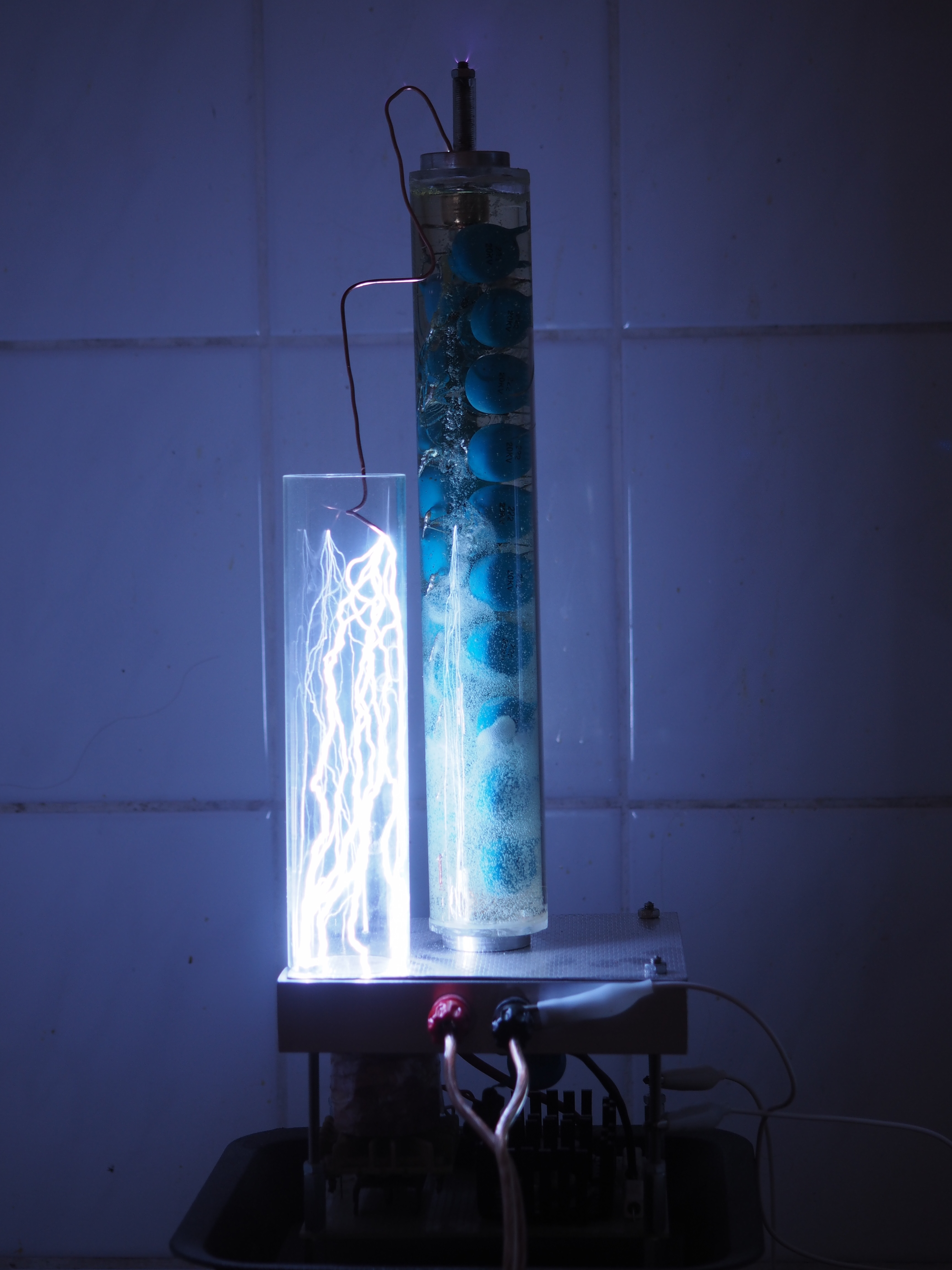
The second cascade was build using 20kV 2.2nF capacitors and 20kV rectifiers, thus resulting in a maximum output voltage of 200kV. At such high voltages, corona discharges become a significant problem. Therefore, the assembly was put in a 4cm glass tube, filled with epoxy and both ends are sealed with acrylic glass. Terminals for ground and high voltage output are made from aluminum discs with threads for mounting on the driver base. To provide the AC to power the cascade, electrical feedthroughs are made of M4 threaded rods and glass tubings.
As I did not provide any cooling a lot of bubbles build up in the epoxy and the glass tube cracked. This is no practical issue and gives the cascade an interesting look.
The first driver was based on the same circuit as the 40kV one but on full load, the transistors failed within seconds. After a friend of was laughing at me for the small cooling fins and after some explanations, I realized, that the transistors are mostly driven in linear mode, where they are regulating the current. In this use-case, they dissipate lots of power.
ZVS Driver Update
The new Driver for the Cascade was based on the ZVS circuit using IRFZ44N which can handle 49A/55V @ 94 W. As the FETs have an RDS of only 17mOhm they dissipate less heat than the 2N3055 transistors. In addition, the ZVS circuit switches if the voltage across the FETs is zero. At 15V the driver draws up to 10A without any problems.
As this circuit has no feedback loop, it can also be analyzed in LT-Spice. Especially if the concrete values are known.